Sequential Quantum Gate Decomposer (SQUANDER) package provides static and shared libraries (located in the directory path/to/installed/qgd_python) that can be linked againts our own C++ code. In the forthcoming sections we provide some tricks and best practices to use the SQUANDER API. Also, the SQUANDER API is supprted by a Doxygen documentation, which can be accessed trough the file path/to/qgd/Docs/html/index.html. (To build the Doxygen documentation follow the manual at Main Page.)
A succesful build of the SQUANDER library can be tested by running the test cases in the path/to/qgd/test_standalone directory. (To build and install the SQUANDER package follow the manual at Main Page).
The expected outcome of the test program decomposition_test.cpp should look as:

The output informs us that the 4-qubit unitary was decomposed by using 75 CNOT gates with decomposition error 0.000316. These information are followed by the list of the decomposing operations.
Using the SQUANDER library
In this example we show how to use the SQUANDER library for developing applications using the decomposition capabilities of the SQUANDER package. Here we explain the steps provided in the example file decomposition_test.cpp to decompose a general random 4-qubit unitary.
To include the functionalities of the SQUANDER package, provide the following lines in your code:
The first include provide basic functionalities of the SQUANDER package, for example methods for aligned memory allocation and memory release. The second line includes the definition of the class to perform the decomposition of the N-qubit unitaries. This class is the key element to access the decomposition capabilities of the SQUANDER package. The third line imports the method and class definitions for creating random unitaries to be decomposed.
The SQUANDER package provides two ways to create random unitaries. The first way can be used to construct a random unitary as a product of CNOT and U3 operations. The parameters of the operations are chosen randomly, but the overall number of CNOT operations is predefined:
The code snippet above demonstrates the way to create a random unitary describing qbit_num qubits and constructed from cnot_num number of CNOT operations. The constructed unitary is returned through the preallocated Umtx_few_CNOT array. The second method can be used to construct general random unitaries based on the parametrization of arXiv:1303:5904v1.
After the creation of the unitary to be decomposed we create an instance of class N_Qubit_Decomposition to perform further calculations:
Notice, that we gave the complex transpose of the unitary Umtx as an input for the class N_Qubit_Decomposition. This can be explained by simple linear algebra considerations: since the product of the unitary with it's complex transpose ( \(U U^\dagger=I\)) gives identity, the sequence of operations bringing a unitary \(U\) into identity would naturally equal to the complex transpose \(U^\dagger\) of the unitary \(U\).
Along with the input unitary we provided two other inputs for the decomposition class.
- optimize_layer_num Set true to try to find the fewest number of CNOT gates necessary for the decomposition (increasing the running time) or false when the predefined maximal number of layer gates is used for the decomposition (which fit better for general unitaries).
- initial_guess String indicating the method to guess initial values for the optimization. Possible values:
- ZEROS: the initial guessed values are all zeros,
- RANDOM: the initial guessed values are random doubles,
- CLOSE_TO_ZERO: the initial guessed values are random numbers close to zero.
In case we would like to try to minimize the number of CNOT gates in the decomposition, the best choice for the initial_guess values are ZEROS (discussed in more details in the forthcoming sections). However, this kind of the choice might result unwanted convergence of the optimization to local minimum instead of the global one. Thus, the solution of this example might sometimes fail to reach the global minimum. For the same reason, unitaries consisting of much CNOT gates can be well decomposed by initial guess values RANDOM or CLOSE_TO_ZERO.
Finally, before we start the decomposition, we set some other parameters for the decomposition:
By setting the number of identical blocks in the code snippet we order the code to use two identical successive blocks for the sub-disentanglement of the 4-qubit unitary:

and do not use repeated successive blocks in the decomposition of the 3-qubit submatrix:

The idea behind setting two identical successive block is very straightforward. In this case the successive CNOT gates might cancel each other resulting in possible simplification of the gate structure in the end of the decomposition process. Notice, that setting more the three identical blocks has no sense, since all two-qubit unitaries can be decomposed with at most three CNOT gates.
In the second part of the code snippet above we set the maximal number of operation blocks allowed in the n-qubit sub-decomposition problem. The demonstrated choices correspond to the number of layers needed to the decomposition of general N-qubit unitaries. (These maximal parameters are in-built in the code, it is not necessary to provide them in the code.) In more specific problems the unitary might be decomposed by fewer CNOT gates. In such cases we can define the upper bond of the decomposition operation blocks via these settings.
The third part in the above code snippet is about the setting of the number of iterations in each optimization step used during the sub-decomposition of the n-th qubit. By default, the number of iteration loops are set to one, however in case of specific unitaries, it is advised to increase the number of iteration loops to avoid unwanted convergence to local minima. (On the other hand, the increase of the iteration loops might increase the running time.) We notice, that the best choice of the above parameters varies from problem to problem. One should give a try to multiple set of parameters to find the best decomposition of the unitary.
In the last command of the code snippet above one can set the verbosity of the decomposition to on/off by the value True/False. After setting the parameters of the decomposition we can start the optimization process by the command:
The last command in the above code snippet prints the decomposing operations into the standard output. For further programming usage the list of decomposed operations can be retrieved via the method N_Qubit_Decomposition.get_operations of the class N_Qubit_Decomposition.
Defining custom gate structure for the decomposition
The SQUANDER package is not limited to specific choice of the gates used in the decomposition. The decomposition can be executed with arbitrary, but parameter-less two-qubit controlled gates, and with a self-designed gate staructure adopted to the underlaying hardware design as well. Here we provide a simple guide on how to define custom gate structure. A working example is provided in example file custom_gate_structure_test.cpp.
First we create a class that will hold the design of one period of the decomposing gate structure. (This period is then repeated in the quantum circuit.)
Then we can initialize the label of the qubit we need to disentangle. (SQUANDER always disentagles the qubit with the highes label.)
The custom gate structure can be constructed using a for loop:
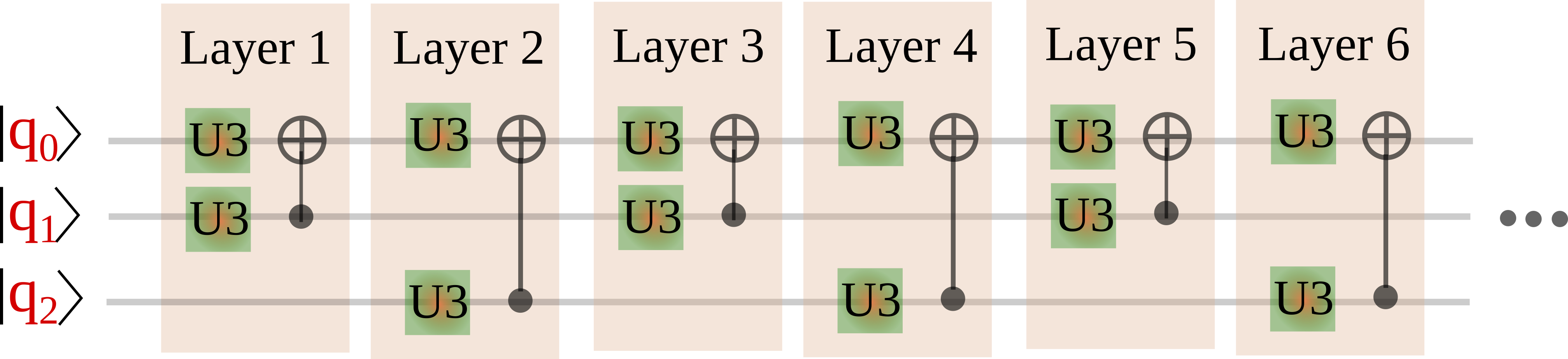
In the individual layers (defined again by an instance of class Gates_block) we can choose between qubits to play the role of the control and the target qubit on demand. Whatever is our choice, we should apply U3 gates to the qubits in front of the chosen two-qubit controlled gate. The U3 gates should have two free parameters, lets say variable Theta and Lambda, while parameter Phi is kept constant zero during the decompsition. (Parameters set to True are free parameters, while parameters set to False are kept constant.) In the first "if" body a connection between qubits 0 and 1 is created via a CNOT gate. In particular, qubit 0 is chosen as the target qubit, and qubit 1 is chosen to be the target qubit. (The oriantation of the two-qubit controllod gates can be reversed, so the specific choice of the roles of the target and control qubits is not important in principle.)
The second "if" body controls the gate structure between any other qubit pairs. The created layers are added to the gates_block which can be used to decompose a quantum program. The figure below shows the period of the constructed gate structure in case of three qubits
We continue by creating a random 3-qubit unitary (and its transpose conjugate) by code snippet:
Then, we create an instance of a class to decompose the unitary
and we set the constructed gate structure to be used in the decomposition
In order to disentangle the 5-th, 4-th, 3-rd or the n-th qubit we may use different gate structure, each of them should be defined as a pair element in a C++ map gate_structure. Finally, we start to decompose the unitary and show the results.
